The Project
A neurobiological research lab at Neurobiology of Aging Department @ ISMMS uses complex brain implants which record brainwaves from specific neurons. The lab personnel have to make both the implant components and the implants themselves through a very labor-intensive and error-prone process.
My job was to simplify the assembly process, develop new techniques to expand implant configurations and eliminate as many errors and imperfections as possible. I discovered optimal intervention points in the assembly sequence, optimized protocols and introduced 3D-printable designs.
The resulting designs and practices reduced production time by over 3 hours per implant, eliminated waste of parts and labor at several key steps, increased scientific efficiency of the implants, and even improved lab environment by reducing noise and dust.
Audit & Analysis
This project required an in-depth understanding of the labs' specific requirements for the brain implants they used and the reasoning behind each choice that contributed to the implant configuration at the time. While the assembly process was causing the lab issues and losses in money and productivity, the basic design, although rigid and limiting, worked quite well. So, as a first step, I familiarized myself with the existing implant design.
Having studied the physical object at the core of this project, I took my usual first steps of discovering business goals and user needs and observing the existing assembly practices and techniques to identify the most problematic areas of the process.
Stakeholder and User Interviews
The reason for the project was the inferior implant build process that limited the configurability of the implants and yielded a high percentage of damaged/unusable parts.
In order to get a good grasp of the process, I conducted a series of interviews with the lab management (stakeholders) and staff responsible for the assembly process and subsequent implant use (end users of the assembly process improvement).
Although this project had significantly more specific constraints than most, the end users' needs closely coincided with the general business goals, making it easy to identify optimal strategies and set up a clear agenda acceptable to everyone.
Business Goals:
- Reduce manufacturing errors & wasted materials/time (reduce assembly costs).
- Expand options for implant configurations (expand research opportunities).
- Reduce assembly effort & time (free up valuable human resources and lab space).
User Needs:
- Simplify assembly process & post-assembly cleanup efforts. ≈ B3
- Reduce noise, chemical smell and dust. ≈ B3
- Minimize troubleshooting efforts. (Improve reliability of assembled implants.) ≈ B1
- Reduce animal training efforts. (Expand recording capacity and reduce implant's size and weight.) ≈ B2
Constraints & Specs:
- Minimize R&D costs.
- Preserve physical properties of materials, especially electrical conductivity.
- Maintain end product stability & reliability through all new configurations.
- Preserve individual electrode height adjustability on the same level of precision.
Contextual Observations:
I conducted in-lab observations of the assembly process to identify specific pain points and most problematic steps. My observations provided a roadmap for the subsequent interventions and redesign plan.
I also observed the brain implants in use during and after the surgeries in a series of typical scenarios. Although unrelated to the assembly process itself, these observations gave me important insights into the restrictions and specifications for the implants. I was also able to set up better tests of our prototypes' viability by creating realistic simulations.
While observing the implant creation process I found that the process could be divided into two parts: manufacturing of components and assembly of components.
While the assembly was complex and time consuming, it incorporated component testing and verification techniques. In most cases, testing and verifying a pre-assembled part would take nearly as much time. Automating these activities would not be cost-effective and in some cases would be simply impossible.
The manufacturing of components, however, could be automated, outsourced or both, - freeing up lab resources and eliminating manual labor and errors.
Therefore, I focused my optimization efforts on the manufacturing part of the assembly and tackled the most problematic of them.

Assembly Journey Map:
This partial journey diagram shows the areas of the assembly process that I found to be most problematic for the users, but easiest to fix via 3D-printing technology. After I presented these findings to the stakeholders, we decided to focus on fixing the problems outlined in this diagram.
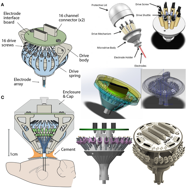
Competitor Analysis:
While deciding how to improve the in-house implant build, we considered using designs from other labs, but unfortunately, none of them were an exact match to our needs. Nevertheless the information I gathered helped us better define the specific parameters for our designs and provided some ideas for the manufacturing methods we might want to try.
There are many labs around the globe doing similar research and using similar implants, but each lab's specific study dictates different design choices.
For example, studies in different brain areas do not require same level of precision when moving the electrodes within the brain, or they might require fewer electrodes to be implanted, thus eliminating some of the weight restraints we were facing, etc. In the end we weren't able to find any existing solutions for our requirements.
Findings Summary:
Existing solutions:
- Most are designed for fewer electrodes.
- The ones with enough electrodes don't offer precision lifting-lowering mechanisms.
- Encasement structures add considerable weight to the implant.
- Commonly used screws are either not precise enough or very large and heavy.
- The 3D-printed drive links are too wide for our density and final implant diameter requirements.
Existing techniques:
- 3D printed implant bases allow for multiple modifications.
- Segmented construction allows for on-the-fly alterations at time of assembly.
- Snap-in nuts allow simple assembly and precise lifting-lowering control, but there are no snap-in nuts for the small and light screws we'd want to use. However, using heavier screws increases implant weight beyond our desired limits.
Conclusion:
Transition most or even all plastic parts to 3D printing.
Retain multi-part base structure to allow variations.
Use snap-in nuts or an alternative to avoid implanting nuts into a mold and simplify assembly.
Find alternative materials or designs for the drive links to eliminate manual cutting process.
To allow greater adjustability of total height, keep the drive stage/body short and adjust the final implant height through the post and the electrode array/bundle height and its cement encasement.
Resources and Costs Research:
Once I established the overall goals of the project and determined that the existing solutions on the market would not fit them, I set out to find the best and cheapest options for custom production. I kept an open mind and researched everything from ordering new molds to improve the pre-existing production methods to completely new methods such as metal and advanced material 3D printing. In doing so I was looking for a sweet spot between production ease and production cost.
I reached out to a wide range of manufacturers, from established industry leaders to starting out one-man-operated 3D printing shops and then evaluated the list of best-offer quotes for either R&D phase(per-iteration) or at scale production options (per-item costs for 300, 1000, 5000 and 10000 items orders.)
Findings Summary:
- Mold-based Creation: ~$3000-$10000 per mold variation depending on part size and complexity. Not an option for the R&D phase, but could be an option for at scale production of simple and common parts such as drive links.
- Stamping: ~$3000 per drive-link stamp shape variation. Not an option for the R&D phase, but could be an option for at scale production of simple and common parts such as drive links.
- 3D Printing: ~$3-$300 per part, depending on size and material. (More expensive for high fidelity materials such as metals and high-end plastics, which require higher-end printers - prices start at ~$20-$50 per tiny part) Also, some at scale orders might provide per-item price reduction for small parts.Great option for R&D, but all materials require thorough testing before real parts can be made this way.
Solutions
After my preliminary research one thing became very clear: this project required a dedicated team and a good plan for minimum viable product (MVP) designs which would satisfy some assembly improvement needs right away and provide testing opportunities for subsequent solutions.
Building a Team:
Throughout my initial research phases I recruited the help of the lab technician with most knowledge about assembling and using the implants. Around the time of my resources research I discovered that our institution was creating a new department for Rapid Prototyping with their own 3D printing shop, laser cutting and machine cutting facilities. I built a strong collaboration with the engineers from the new department, and eventually added to our team a more experienced engineer from the institution's mechanical engineering shop.
This group of 2-3 engineers, a technician and me (as a designer) was responsible for all designs delivered for this project. In addition to my design work I took on project management duties, organized larger design meetings of the team with researchers and stakeholders, and coordinated the administrative efforts to keep the multi-departamental team in line with the institution's regulations.
The team shared responsibilities throughout the entire production process from ideation to final product delivery:
The Technician: After providing crucial input about the implant's key features during the design conception phases of the project, the technician also tested all the design iterations to ensure compliance with all the requirements for the final implant.
The Engineers: The engineers assisted with the choice of materials, methods and tools to deliver all parts up to spec, conducted their own material and techniques experiments for the project and manufactured the implant parts.
UX Designer / Project Manager (me): Conducted product, usability and material research, created designs and 3D models for each design iteration based on specs from technicians, stakeholders and users, ensured clear communication between all parties, managed budgeting, costs and project schedule.
MVP Strategy:
My Minimum Viable Product (MVP) strategy was based on the 3 most problematic assembly areas identified in the Assembly Journey Map above. The goal was to eliminate the most assembly steps as soon as possible while using each successful design to gain useful information for the subsequent products.
As soon as we got to the minimal proof-of-concept point or gained enough insight in each stage of our MVP development, we initiated concurrent work on the next MVP. This multi-sub-project workflow was enabled by the good distribution of roles within the team. However, I continuously made sure that all sub-projects were moving forward at a good pace and that any drastic alterations or developments in new versions of each sub-project were reflected and accommodated by the other sub-projects, so that all the different parts could always be tested together in a fully assembled working implant.
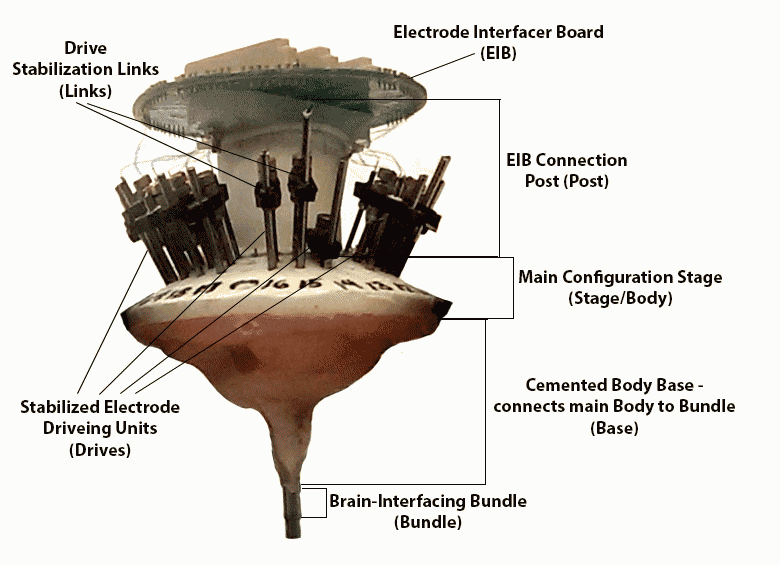
MVP-1: The Post
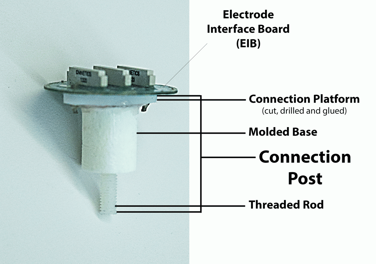
This seemingly simple and unimportant part of the structure is responsible for keeping the whole implant straight and stable. Any mistakes in the process of making this part render the result unusable. The old production method provided ample opportunities for mistakes:
- Acrylic mixing for the mold
- Hand held threaded rod insertion
- Manual cutting of the top platform for EIB connection
- Manual drilling of holes at exact distance from center
- Manual attachment of top platform to molded base with glue and screws
It's a lot of manual, time-consuming, messy and error-prone labor - just for a connection piece between the 2 main players of the implant (the EIB and the drive-housing stage).
Eliminating just this one part from the manual assembly line-up would instantly speed up the entire process ( ⇢ B3, U1), reduce the number of errors and wasted effort and materials ( ⇢ B1, U3), and eliminate noise and dust from drilling and cutting ( ⇢ B3, U2). It was an obvious choice for the first MVP.
In addition to improving the assembly process right away, this choice of the first MVP also enabled us to test the viability of the 3D printing solutions on the safest ground. Lacking internal cavities or complex elements, the connection post is a simple solid body perfect for 3D printing.
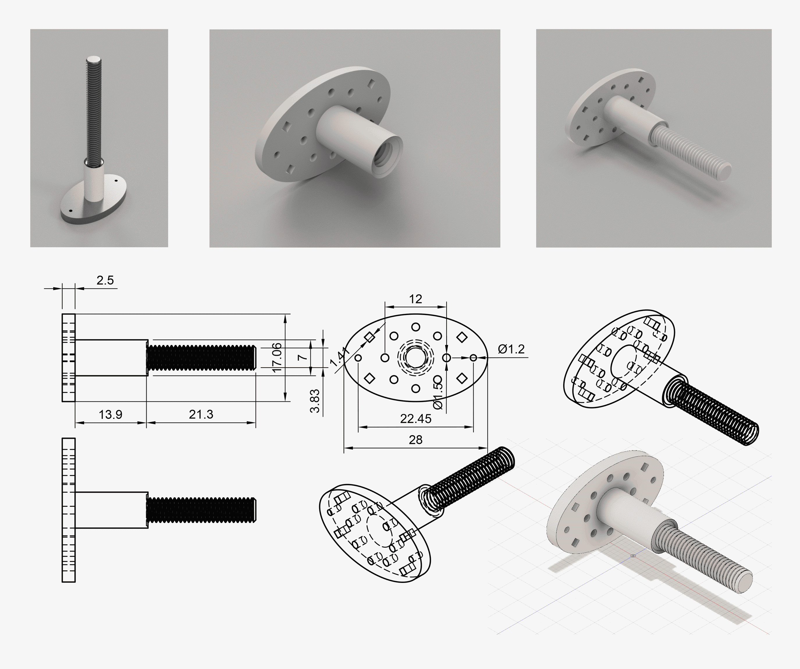
Prototypes:
I designed and 3D modeled several prototypes for the post. The basic structure of the object was very clear from the very beginning as we were eager to ensure that the prototypes could be immediately integrated into the assembly procedures as soon as a working model was found.
As soon as the material tests were done on the very first prototype model, we had an object which was ready for implant integration. The later prototypes were mostly experiments with stability (for example: printing the threaded extrusion vs internal threading for using the threaded rods we already had in stock) and minor convenience and weight improvement such as including vents in the EIB connection platform to lighten the structure and allow glue to spread more evenly when the EIB is glued to it.
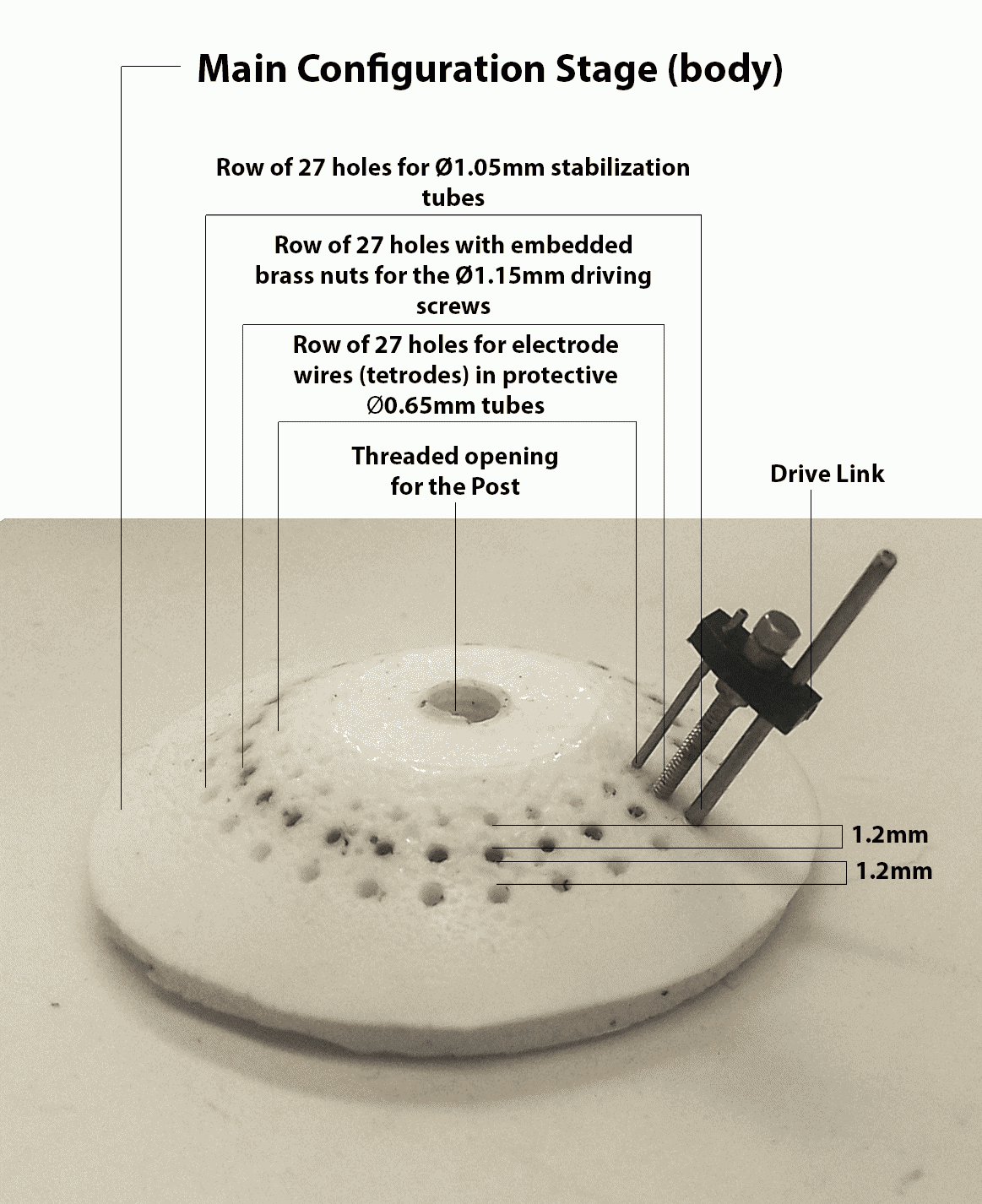
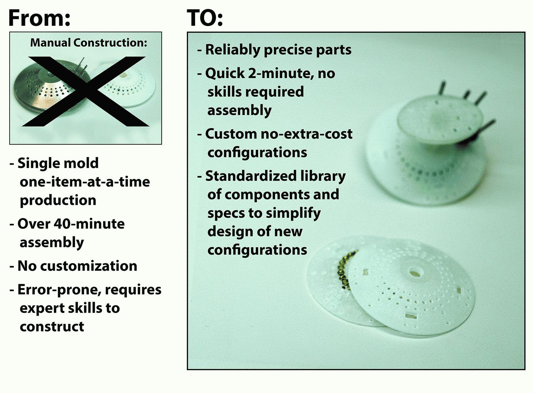
MVP-2: Main Configuration Stage
Converting the main configuration stage for the tetrode driving links from the mold-based production to 3D printing would achieve several important goals:
- Simplify assembly process. ( ⇢ B3, U1, B1, U3)
- Reduce cleanup efforts. ( ⇢ B3, U1)
- Enable easy way for introducing alternative configurations such as increasing the number of driving links per implant. ( ⇢ B2, U4)
The first 2 goals alone would significantly improve the assembly process, since the mold-based production is time-consuming and error-prone, compromising the usability of the results:
- Acrylic mixing for the mold.
- Application of lubricant to metal tubes & screws inserted into the mold to provide size-specific holes in the resulting part. (Uneven application gets the metal parts stuck in the acrylic or produces uneven holes.)
- Placement of nuts on inserted screws - too high or too low results in the nuts being too close to part surface and breaking off when pressure is applied.
- Post-hardening removal of all tubes and screws - part can be damaged if too much force is applied, and parts can get stuck.
Starting with the first 2 goals meant that all we had to do for the first prototypes is replicate the stage model created by the mold-based production. This also meant that these prototypes could be accurately compared and tested against the pre-existing implants. However, even with these first models we could start adding new useful features which were missing in mold-produced stages, such as holes for stabilizing the ground wires.
As soon as we were able to print the first successful designs for the post (MVP 1), we were also able to test our material options and see their limitations. The MVP 1 prints clearly showed that the sturdiest printable plastic we had access to, while being stable on a larger scale detailing, did not provide stable edges for extremely small-scale threading ridges to stabilize the driving screws. This meant that we had to somehow still embed the nuts into the 3d-printed part.
This necessity gave birth to the idea of a 2-part printed stage with nesting for the nuts. The 2 parts could then either be glued together, further securing the nuts in place, or, as an alternative, simply snapped together, removing the need for the glue and dangers of glue-related mess.
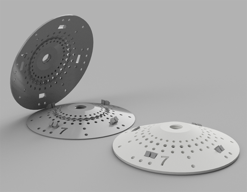
Prototypes:
The initial prototypes I designed and 3D modeled for the configuration stage reflect our attempt to keep the 3D printed versions close to the mold-based stages. Most variations revolved around additional holes and designing a sturdy snap-close fixture.
As we continued the development into MVP 3, this branch of the project got further updates when we decided to change the drive link configuration. Once we had the proof of concept for the basic working stage model ready for immediate use, we could alter and test different configurations of the stage by adding an option for more drive links, especially since the new links easily enabled this option without adding to the overall size of the implant.

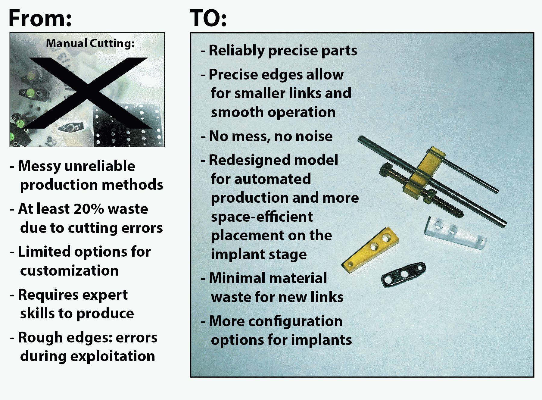
MVP-3: Drive Stabilization Links
Providing working solutions for MVP-1 and MVP-2 would cut over 1.5 hours from the assembly process and significantly reduce cleanup efforts and defective part waste. However, we were still left with the manual stabilization links cutting, which caused noise and dust pollution, while producing unreliable results and many defective parts.
Finding an automated way of producing the links within our institution's facilities would cut costs, save time, remove the noise and pollution within the lab space and, hopefully, reduce material and effort waste ( ⇢ B3, U1, B1, U3). However, we left this task for last, because we wanted to tackle it while building on the knowledge we gained from manufacturing components for MVP-1 and MVP-2. We needed all this background as a team, because optimizing link manufacturing presented us with more challenges than our previous projects:
- Extremely small scale of the part(link).
- Despite the small size the links get a lot of wear and tear during the implant's lifecycle, withstanding stress from pressure and friction, and they need to hold up without cracking or deforming for months of exploitation.
- We were further limited in the materials we could use by the necessity to maintain conductive properties of the link.
- The tubes and screws are both soldered and glued to the link and it needs to maintain adhesion and not get deformed from proximity of a soldering iron.
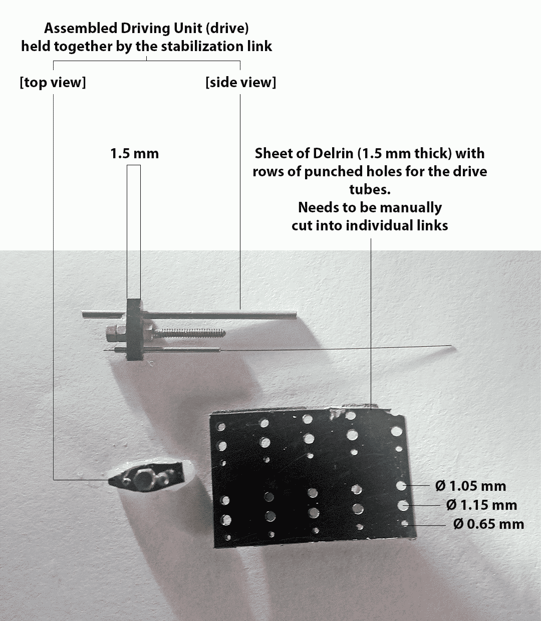
As with other components, our first goal was to emulate the existing design as closely as possible using automation techniques (to ensure that the parts we produce could be immediately integrated into the implant production pipeline). Given the extreme importance of material for this specific component, the replication goal meant working with Delrin. However, 3D printing in Delrin was not an option for our equipment.
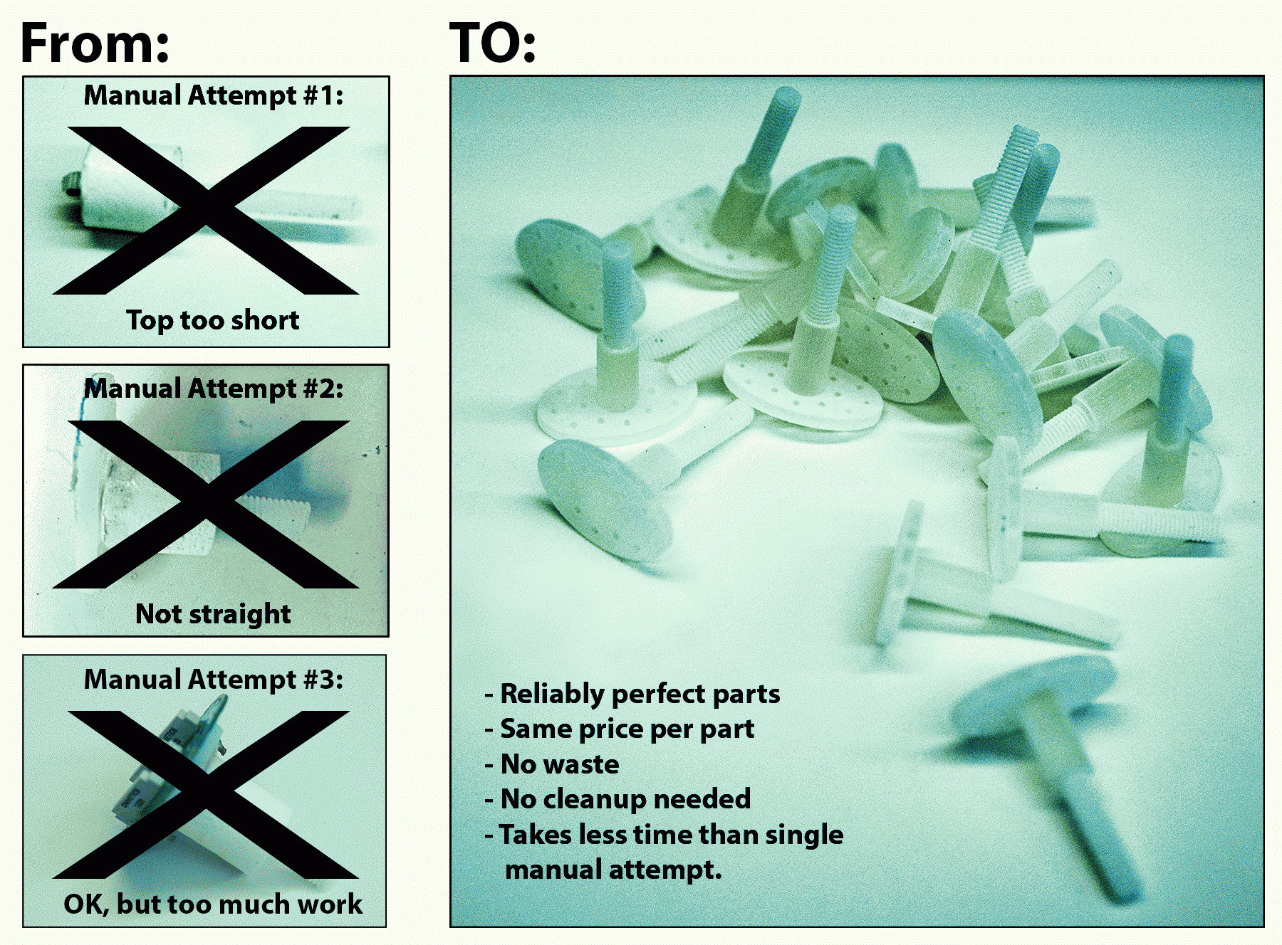
Once I created a digital approximation of the link's design, our engineers tried laser-cutting the links from Delrin sheets. This had mixed results: Cutting many links at once and quickly at this level of precision and scale overheated the material after about 3-5 links, requiring a long cool-off period. Additionally, because of the reaction of the material to heat, not all links were cut with the high precision level we needed. This made the laser-cutting production method very expensive, especially since each implant needed about 30 links.
Although more expensive and error-prone than we would like, this method still allowed us to produce enough usable links to remove the need for manual link cutting while we worked on alternative link production solutions.
I designed several 3D model prototypes for the link. While the holes' diameters and distances were kept the same, I varied the link's width and the thickness to test different materials and their stability margins. The engineers then used these designs to test multiple materials and production techniques.
At the end of the material experiments we narrowed down our material options to Delrin, Ultem and Polycarbonate. Unfortunately, 3D printing these materials on the required scale is too expensive (over $18 per link). Given that our project's goal was to eventually increase the amount of drives per implant, these costs would be too high for our purposes.
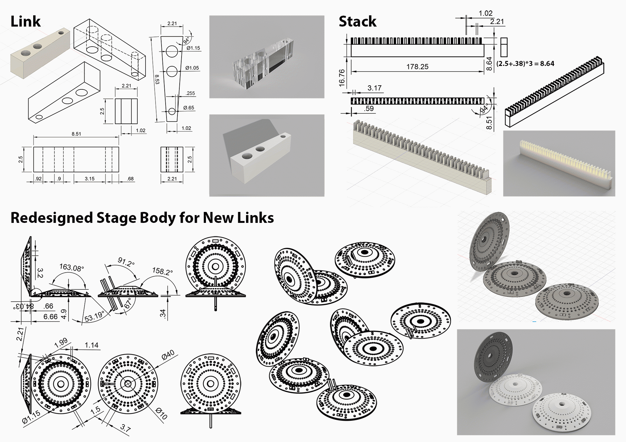
Machine-cutting was an alternative technique that the engineering team decided to explore. However, cutting the links with either rounded or complex shape would again significantly drive up the costs, making this process not cost-effective. This prompted an alternative redesigned solution - both for the links and the configuration stage (to accommodate the changed link) Together with our engineer from the mechanical shop we came up with a wedge-shaped link. The wedge-shaped prototypes, when tested, proved to be both strong enough and effective enough in maintaining the high-precision lowering and lifting of the tetrode wire tube connected by the link to the driving screw. The new design links needed to be a millimeter taller to retain their strength, but they also provided a more efficient shape for placing more drives into the stage body. We were able to increase the number of drives to 36 for the new configuration stage, moving our MVP-2 further towards achieving the overall project goals ( ⇢ B2, U4).
Once the wedge-shaped link prototypes proved to be a viable solution, we turned our attention towards automating and scaling their production. I designed a stack of wedges placed on a zig-zag formation and spaced ⅛ inch apart to be cut from a pre-cut-to-size blocks using a programmable CNC drilling machine with 5 distinct tool-heads per run: 3 drills for the specific diameter holes on each link, ⅛ inch drill head to cut out the spaces between the links and a thin trim saw blade to cut off 2.5mm slices from the cut shape (each slice being a finished link wedge). With 37 wedges per block and at least 3 links to be cut off from each wedge, a CNC run on a single block (without manipulations or adjustments to the block itself) would yield 3 implants' worth of links, finally providing us with a cost-effective solution.
Prototypes:
For the initial pre-existing link emulation we created several prototypes to experiment with link wall thickness around the 3 holes and the overall shape of the link (more rounded vs more angular). The same shapes were used for both 3D-printed material tests and the laser-cut Delrin links.

Once we settled on the redesigned wedge shape, we also needed to design a stack for convenient CNC cutting and a stage that would accommodate drives with the altered configuration of tubes and screws.
Tests & Results
I assigned and sequenced our MVP projects so that each MVP, if successful, would provide immediate benefits for the production, but even regardless of success, the project would also provide important testing grounds which would benefit subsequent projects. Therefore even unsuccessful tests proved to be useful down the road and saved us valuable effort and time.
MVP-1 Tests & Results:
Although the design of the post and the part itself were comparatively simple, we did have strong rigidity and stability requirements for it: no chipping, no crumbling, no bending, no breaking. As the element that holds the entire implant together, the post needs to hold up in all sorts of practical situations (my observations of the finished implant in use revealed some pretty unexpected instances of abuse this part needed to sustain). But besides the strength, it also needed to be as light as possible - more solid plastics might be rigid and strong, but hey are also dense and heavy, so a large component of the implant such as the post, when made of heavy material would add too much weight to the final structure.
Tests:
For this product we needed to test the durability of the final part and its performance in a contextual setting. Together with the technician on our team we designed a series of tests for the prototype we tested. While the technician tested the material properties of the prototype as it pertained to electric conductivity and interaction with other adhesives and chemicals involved in assembly and implant surgeries, I developed an evaluation checklist for the durability of the part.
Post Durability test checklist:
Prototype #:_____________
Material: ____________________
Material cost: $___________ / g
Part Weight: ___________ g
Can one of the top-platform holes be broken or damaged by inserting a stabilization rod and applying perpendicular force to it until the rod starts to bend?
□ YES □ NO
Can the threading be scratched off or damaged by the stabilization rod?
□ YES □ NO
Is the threading precise enough to match the fine base threading?
□ YES □ NO
Do the base and the post easily thread together?
□ YES □ NO
When threaded into the base, can the post be pulled out by application of bare-handed force?
□ YES □ NO
When threaded into the base, can the post top be broken off by application of bare-handed force?
□ YES □ NO
Tested by: _____________________
Results:
Due to the large percentage of failing parts in the old manual production techniques, this product was hugely successful in simplifying production. Although, when counting wasted materials and parts vs the material and printing costs , the cost per part ended up being similar (~$30, depending on the printing batch size), when accounting for the cost of personnel time involved in production and cleanup (at least 2 hours of paid work time), the new parts cost 2-4 times less.
In addition to basic costs, stabilizing and simplifying production of this seemingly simple part significantly improved the stability and longevity of the implants and the overall experience of people involved in the implant production.
- 3D printed posts completely eliminated production errors and waste. ⇢ B1, U3
- No more mess and loud machinery running in the lab space for platform shaping and drilling and nothing to clean up afterwards. ⇢ U1, U2, B3
- Reduced post-related steps in the assembly from 10+ complicated steps to just the last 2 simplest steps: 1) Thread into main configuration stage. 2) Attach to EIB using screws and nuts. ⇢ B3 (and, indirectly B1), U1, U3
- Reduced the time of the post-related assembly steps from 40+ minutes (not even counting failed attempts) to under 3 minutes per implant. ⇢ B3, U1, U3
- A single printed batch of about 30 posts can accommodate a multitude of small post variations for different projects: shorter space between threading and EIB platform, more/bigger holes in the EIB platform, etc. All done at the same time, saving time and enabling better choices at time of implant assembly. ⇢ B3, U1
Additionally, through the tests conducted on MVP-1 prototypes we discovered that the most fitting and cost-effective material for our purposes was VisiJet Crystal Plastic. However, the material also had its limitations, such as inability to sustain the fine end-tips of the threading, which made it impossible to print even finer threading required by the small brass screws used in the drives. This informed our decision to embed the nuts into the base as we moved forward to MVP-2. ⇢ C1
MVP-2 Tests & Results:
As soon as the prototype testing for MVP-1 (the post) allowed us to settle on the material of choice and identify its limitations, we began working on the MVP-2 (the configuration stage). Here our tests focused on the reliability of the nut-embedding and completed part stability as well as experiments with small configuration alterations to enable alternative implant configuration (increased number of electrodes to record from, multiple brain interfacing bundles for recording from different regions of the brain, etc.) Once we identified the optimal parameters, we could produce multiple configurations in a single printing batch, significantly reducing the cost of each part.
Tests:
Although this component of the assembly redesign process had far reaching goals of expanding research opportunities through implant customization, one of the most primary goals of converting to the 3D-printed production was to ensure ease and speed of assembly itself. Therefore, some of our tests focused specifically on the speed of putting the 2 stage parts together and the ease of embedding the nuts between the 2 stage layers.
To capitalize on price reduction when multiple items are printed at once, we designed multiple variations of each test iteration. For example, the same batch of designs to be printed together included a 2-part stage with 3 snap structures and a very similar design with 4 snap structures to determine what would be both sufficient to hold the stage together yet easy to align and operate. The same batch would also include parts for a stage with larger nut nests and tighter nut nests to see what is sufficient to stabilize the nests without adding glue and easy to press the nuts into the nests. This way once the batch of designs was printed we could run multiple tests and pick the winning designs to base our next design iteration on. However even the less successful designs could be useful for other tests. For example. the designs with nut nests too large to successfully stabilize the nut for desired rotation precision was used to test the use of different glues to attach the nuts to the nests and test how much this slowed down the assembly, what potential errors this addition step would introduce and how stable the glued nuts became under repeated stress of exploitation.
As multiple members of the team worked on testing each the designs, it accumulated notes, which I later summarized and used to derive standards and components for future design iterations.
Design notes summary example:
Prototype ID#: 0107
Material: VisiJet Crystal
3D Design Filename: Tskirt_v0107_numbered_full
Part Weight (without nuts): 3.62g
Assembly time with nuts and post: under 2 minutes (several interruptions occurred during the test).
Nut nest size? Sufficient and easy to assemble
Snap fixture notes? Sturdy snapping, the hooks are flexible enough to snap without breaking and strong enough not to allow any wiggle room afterwards. Symmetrical placement of the 4 snap structures poses no problems if the numeric cutout on the side of the part is used for alignment.
Ground wire allowances? There provided number of openings is enough, but some configurations might need a different distribution of holes, also more obviously identifiable grouping might ease the process the lining up of 2 parts before snapping. Note: keep the spacing between ground wire holes at 2mm minimum.
Adhesive requirements? This version is stable enough without the use of adhesives especially once threaded through with the post.
Nut stability? Nuts are stable enough to allow full precision screw articulation, but increasing the distance between individual nuts might cause nuts to move slightly through material compression over time. (Test in next iteration.)
Design strong points (standardize):
- Snap hooks shape and size. Filename: Stage_v0107_Snap_Component11
- Snapping fixture design (hooks + positioning and size of opening into which the hooks fit) Filename: Stage_v0107_Snap_Component11 and Stage_v0107_Snap_Component11-a
- Distances between ground wire holes. (minimum 2mm)
- Model ID cut out (for ease of matching and alignment of the 2 parts during the assembly)
- Nut nest sizing(only valid for same distance between nuts arrangements, further testing needed for other designs) Filename: Stage_v0107_Nut-body-base_Component12
Results:
Within the first 2 iterations of 3D-printed design batches we developed working stage models ready to replace the old manually manufactured stages. The new models provided great improvement in assembly time and removed over 200 of small annoying manual and error-prone steps. These working designs were now ready for printing whenever supplies ran low and batched printing meant that we now had a few stages lying around and ready to use, providing useful back-ups in case things went wrong in subsequent assembly process which did not lend itself to automation. These working models also provided useful elements for subsequent designs and configuration modifications.
Our CAD software provided us with tools to build and save a library of pre-made, annotated design elements, greatly simplifying development of new configurations. Although each new configuration still required testing, reliable design elements increased the likelihood that we would get a working model of an alternative configuration within the first printed iteration batch, as was indeed the case when a redesigned MVP-3 triggered a new variation of stage designs.
- Reduced stage manufacturing from 250+ tedious steps, ~60 of which were time-consuming and frustrating, to the much simpler and quicker assembly: 1) push nuts into nests - although technically could be counted as ~30-50 separate steps, depending on configuration, each of these "steps" takes ~1-2 second to accomplish, making this entire process very fast and easy. 2) Align the top and bottom parts of the stage, snap them together. - Done. ⇢ B3 (and, indirectly B1), U1
- Reduced the time of the stage-related assembly steps from ~50-80 minutes to under 2 minutes per implant. ⇢ B3, U1
- 3D printed stages reduced production errors and waste. Off-site production of the stages also improved the lab environment. ⇢ B1, U2, U3
- A single printed batch of at least 15 stages - the smallest cost-effective batch size - can accommodate a multitude of small and dramatic differences in design and configuration. This can be used to combine production with R&D models in the same batch as well as for accommodating varied projects and experiments at the same time. No more need to manually wrestle a standard design into a different shape for a new experiment. No need to share the same mold across projects. Instead we delivered precise solutions for diverse scientific needs. ⇢ B2, U4
Additionally, the development of design standards and best design practices for the scientific goals combined with the freedom gained from easy development and production of new designs allowed us more freedom in redesigning MVP-3 (the links).
MVP-3 Tests & Results:
The links are a crucial element in the implant's stability and durability. Both the materials and the links themselves required extra testing from engineers and technicians to ensure that all the physical properties we required were fully maintained in each new prototype. Eventually these tests narrowed down our material choices to Delrin and Ultem. We also discovered that we could cut down prototyping costs by using polycarbonate to test the models which were intended for Ultem production.
The reliability offered by automated production had a huge impact on the assembly time and efficiency, even though the assembly steps associated with the links did not change. With the manually cut links the users wasted time and fumed in frustration whenever the uneven edges of two links rubbed against each other once they were installed as assembled drives onto the stage. Every time this happened the users faced two unpleasant options: 1) look for another link that would fit better and reassemble the drive or 2) sand down the existing one risking permanent damage to it. These frustrations and waste of time and effort were completely eliminated by the automatically produced links.
Even our laser-cut delrin prototype, while not cost-effective and prone to many damaged parts, was still a huge improvement for the users: although not all links were reliable in hole sizes, their defects were immediately obvious during the initial drive assembly, therefore all the damaged links were discarded early in the assembly process, making the installation of drives on the stage smooth and efficient. Therefore, even our failed prototype provided useful temporary solution to some of the assembly problems, and an immediate improvement to the process as we continued to develop better alternatives.
Results:
Within the first 2 iterations of digital designs for the links we were able to produce a link shape optimal for replacing the manually produced links. Since we tested laser cutting Delrin as one of our first prototypes - in keeping with the motto of sticking maximally close to pre-existing models in our initial R&D attempts - even our failed attempt of producing the links at scale with this method resulted in a supply of several hundred usable links for the immediate needs of implant production.
With the immediate needs satisfied we ventured into bolder modifications of the design and the redesigned links provided even more benefits for the project:
- Automated link production eliminated some of the most aggravating elements of implant production, saved time, eliminated waste of materials and labour, improved lab environment. No more mess and loud machinery running in the lab space and nothing to clean up afterwards. ⇢ B3, B1, U1, U2, U3
- Solved a major pain point and time-sink in the assembly process by providing identical and reliable links. The selection, matching, fine-tuning and placement of every link on a stage took anywhere from 3 to 15 minutes with the manually cut links - with the average being about 3.5 hours for the 27 links on one implant. The new links reduced the effort to under 1 minute. That's an improvement of at least 2 hours per implant. ⇢ B3, U1
- The redesigned links allowed us to place 9 more drives on each implant (increasing the total number of drives per implant from 27 to 36) without increasing the implant's diameter or changing its shape. This more ergonomic shape also provided a significant improvement for the possibilities of customizing the implants for different scientific needs. ⇢ B2, U4